AC3Filter ver $ver |
 English English |
 Russian Russian |
 Italian Italian |
| Donate! | Download | Forum | Source forge project |
AC3Filter is a high quality free DirectShow filter designed for real time audio decoding and processing. It has a priority on wide functionality and convenient settings. Filter can decode following audio formats: AC3/DTS/MPEG Audio. It also supports multi-channel and digital (SPDIF) outputs.
Run the installation program and follow the instructions. Additional system settings may be required for using of multi-channel modes and digital output mode (refer to 4. System setup).
Run uninstall program from the Start menu or from the Control Panel.
All saved settings of matrices, equalizers, etc. will be lost!
Filter can be installed together with other programs (codec-packs, players�). In this case, filter can be uninstalled only together with that program. If you have no idea about what program filter was installed with or you are going to uninstall the filter but not the program you can uninstall the filter independently as follows:
This section describes one-time settings, which should be made after the filter installation. The most compatible operation mode is 16-bit stereo mode (not multi-channel), which is the default filter operating mode. This mode is compatible with all Windows versions and all audio cards. There is no need for additional settings to operate in this mode. For operating in multi-channel modes and in digital output mode some system settings may be required.
| Win95, Win98 | Win98SE | WinNT (3) | Win2000 | WinXP | |
|---|---|---|---|---|---|
| mono/stereo 16bit | + | + | + | + | + |
| multichannel | - (?) | WaveOut (1) | SP6 | + | + |
| SPDIF | - (?) | WaveOut (1) + ���� (2) | - (?) | SP2 | + |
Configure speakers in filter settings (refer to 6.2. Main settings). Some audio cards operates incorrectly with odd number of channels (for instance, 2/2+SW 4.1 quadro or 3/0 3 front). Therefore, such modes should be avoided, if possible. Dolby Surround/ProLogic and Dolby ProLogic2 modes are not multi-channel modes. Moreover, modes with subwoofer (2/0+SW 2.1 stereo, 4/0+SW 4.1 quadro) should not be used if acoustics has no separate input for subwoofer (refer to 7.2. What is LFE?).
Set speakers mode in Control Panel->Sounds and Multimedia->Audio->Sound Playback->Advanced. Furthermore, audio card drivers often have their own utilities for switching of speakers configuration. It is necessary to set the proper configuration at both locations - within audio card driver settings and within the Control Panel.
For Creative audio card it is necessary to switch off all sound effects and equalizers, otherwise there can be a loss of central/rear channels.
Audio card can operate in two modes: DirectSound and WaveOut. In some cases, the multi-channel mode can operate only in one of those modes and cannot operate in another one. If that is the case, output device should be changed in player settings. To get information whether the player supports the device changing function, refer to the table of compatibility in 5. Player setup section (Renderer column). If the player has no such function, it is possible to change the default system output device (refer to 6.5. System settings ). However, this option changes the global system settings; therefore, it is recommended to use it only if the player does not support the mentioned function.
SPDIF mode is required only in case of digital connection to external decoder/receiver exist. It is important previously to ensure whether the receiver connected correctly (refer to audio card and receiver documentation).
It is necessary to check SPDIF box in filter settings to switch the SPDIF mode on (refer to 6.2. Main settings)
Digital connection supports different formats of data transfer (PCM, AC3, DTS, MPEG Audio). Refer to receiver documentation to get information about the formats supported by receiver. In most cases only AC3 format is supported - if that is the case, there is no need for additional settings (it is active by default). If the receiver supports some other formats, they can be indicated in filter settings (refer to 6.5. System settings ).
Some drivers have an ability of AC3 decoding. If such option is available it should be disabled (refer to audio card manual).
Audio card can operate in two modes: DirectSound and WaveOut. In some cases, the SPDIF mode can operate only in one of those modes and cannot operate in another one. If that is the case, output device should be changed in player settings. To get information whether the player supports the device changing function, refer to the table of compatibility in 5. Player setup section (Renderer column). If the player has no such function, it is possible to change the default system output device (refer to 6.5. System settings). However, this option changes the global system settings; therefore, it is recommended to use it only if the player does not support the mentioned function.
Most of audio cards can operate in digital transfer mode only with 48000 Hz sample rate. Therefore, in all other cases the digital transfer is impossible at all. Current digital output mode can be checked during playback on the Main page of filter settings (refer to 6.2. Main settings)
If acoustics has no separate input for subwoofer, modes with subwoofer ( 2/0+SW, 4/0+SW) should not be used (refer to 7.2. What is LFE?).
It is recommended to activate bass redirection for the modes with subwoofer. In acoustics documentation, information about bandwidth of speakers and subwoofer should be found; it is recommended to set the cutoff frequency equal to lower bound for main speakers and to upper bound of subwoofer. For instance, if the bandwidth of main speakers is 100 Hz - 20 kHz and that of subwoofer is 30 Hz - 100 Hz then the cutoff frequency must be set at 100 Hz. In most cases, the default setting is satisfactory, so there is no need to change anything.
Some audio cards have their own bass redirection control settings. It is not recommended to activate both options at the same time! This can result in significant distortions. Bass redirection must be switched on either in filter only or in audio card settings only.
After installation filter has already all settings and in general, it does not require any additional settings. Therefore, if you are not familiar with it, do not make any changes. It is recommended to modify settings only if there are some problems with sound. However, if you are inquisitive and you like to play with settings, please, refer to 7. Theory section.
This section briefly describes the most known players and possibility of their operation together with AC3Filter, abilities of players and required settings.
| Player | Abbr | Site | License | AVI | DVD | Filters | Renderer | Decoder | Supported | Details |
|---|---|---|---|---|---|---|---|---|---|---|
| Media Player Classics | MPC | (site) | OpenSource | + | + | + | + | + | + | (details) |
| Windows Media Player v6.4 | WMP64 | (site) | Freeware | + | - | + | - | - | + | (details) |
| Windows Media Player 7+ | WMP7+ | (site) | Freeware | + | + | - | - | - | + | (details) |
| BSPlayer | BSP | (site) | Freeware | + | - | + | + | + | + | (details) |
| ZoomPlayer | ZP | (site) | Freeware | + | - | + | + | + | + | (details) |
| ZoomPlayerPro | ZPP | (site) | Shareware | + | + | + | + | + | + | (details) |
| LightAlloy | LA | (site) | Freeware | + | + | + | + | - | + | (details) |
| PowerDVD WinDVD |
PDVD WDVD |
(site) (site) |
Shareware Shareware |
+ + |
+ + |
- - |
- - |
- - |
AVI only AVI only |
(details) |
It is clear that the table is far from being complete, therefore any corrections and additions are welcomed.
It is one of the most multifunctional players. Though it has a simple look and a small memory size (~1Mb), of player surrenders only ZoomPlayer by functionality. Furthermore the player has a great number of internal decoders (there is no need to install any codec-packs and other external decoders). It supports DVD playing, Flash animation (with rewind function!), RealVideo/RealAudio, QuickTime and many others. This player is reliable, stable and has no special requirements for resources (my favorite player :-).
During watching filter settings can be called by right button click on the frame, then select Filters->AC3Filter in drop-down menu:

Player settings can be called from View->Options menu. To make the player to use AC3Filter player settings should be changed as shown in the figure:

If there are several decoders installed in the system, decoder with the highest priority will be in use. To modify the filter priority, refer to 6.5. System settings . The player can be configured for continuous use of AC3Filter independently of current system settings. For that, enter the Overrides section of player settings, press AddFilter button and then select AC3Filter from the list. That will result as follows :

Simple player delivered within all Windows versions from Win98 (Win98, WinME, Win2000, WinXP, ...). Player is located at C:\Program files\Windows Media Player\mplayer2.exe. This player is extremely reliable, has no special requirements for resources and utilizes standard playback methods only; therefore, it is essential for detection of different problems. Many functions are not available but the player excellently copes with its general task - file playing. If there, any playing problems appear when using other players it is recommended to try this player.
During watching filter settings can be called from File->Properties->Advanced menu:

Player has no settings for specific AC3Filter use, therefore if there are several decoders installed in the system, the decoder with the highest priority will be in use. To modify the filter priority, refer to 6.5. System settings.
This family of players has no ability of calling the filter settings during watching. Thus, you cannot know whether AC3Filter or some other decoder is in use. Also, you cannot change the settings and monitor the current activity (properties of current audio stream, input/output levels, DRC activity, etc.) during playing. The single exception is the Windows Media Player 9 in DVD playing mode only. In this case, the filter settings can be called from Tools->Options menu (this option will not take effect when watching .avi files or files of other formats).

In all other cases, it is possible to configure the filter only by configuration utility before watching the film.
Player has no settings for specific AC3Filter use, therefore if there are several decoders installed in the system, the decoder with the highest priority will be in use. To modify the filter priority, refer to 6.5. System settings .
Multifunctional player with skins support.
Filter settings can be called by right button click on the frame. Then select Options->Filters->AC3Filter in drop-down menu:

Player settings can be called from Options->Preferences menu. To make the player to use AC3Filter you should change player settings as shown in the figure:

This is the most multifunctional player. There is no sense to specify all functions because of their great number.
Filter settings can be called by right button click on the frame. Then select Filter Properties->AC3Filter in drop-down menu:

Filter settings calling is shown in the picture:

Player has no settings for specific AC3Filter use, therefore if there were several decoders installed in the system, the decoder with the highest priority will be in use. To modify filter priority refer to 6.5. System settings .
Both players cannot use the AC3Filter to play DVD. It�s concerned with the players features, therefore it is impossible to force them to use AC3Filter. That is no ways in principle to force those players to operate with AC3Filter! So to watch DVD with AC3Filter use it is recommended to use other players - Media Player Classics, LightAlloy or ZoomPlayer.
When playing AVI-files by these players you can use AC3Filter both for post-processing and for AC3/DTS audio track decoding. However, the player cannot call the filter settings, so you should configure the filter by configuration utility before watching only.
After installation filter is already well-configured and in general, it does not require additional setup. Therefore, if you are not familiar with it, do not make any changes. It is recommended to modify the settings only if there are some problems with sound. However, if you are inquisitive and you like to play with settings, please, refer to 7. Theory section.
There are two principal rules of configuring:
You should enter the filter property window to configure the filter. There are two ways to do that:

This page contains most essential filter settings and information about audio playing. Information and levels are displayed when calling the settings from the player only:

This section describes the settings of filter output format. Filter will automatically convert all input formats into defined configuration. Speakers' configuration is represented in the form of front/rear+subwoofer. There are conventional names for some configurations. For instance, 2/0 - stereo means 2 front speakers, i.e. stereo. 2/2 - quadro means 2 front and 2 rear speakers, i.e. quadro. 3/2+SW 5.1 channels - 3 front speakers, 2 rear speakers and subwoofer - 5.1 configuration. It is desirable for defined configuration to be in accordant with the system settings (refer to 4.2. Setup for multichannel mode ), which in turn must match with the actual number of speakers. To know the difference for subwoofer and for LFE channel, and how to set configuration, refer to 7.2. What is LFE? section.
Dolby Surround/ProLogic and Dolby ProLogic II modes are required only when computer has stereo output only and is connected to Dolby ProLogic decoder. In this case, central and rear channels are mixed into two channels to let external decoder to extract them from those two channels backwards. This is not a multi-channel mode! This is a special type of stereo mode required only if the external Dolby ProLogic decoder exists.
The second selection list sets the sample output format. Filter will automatically convert any input format into defined one. When decoding the filter defines decoding precision. At present 16/24/32 bit and floating-point formats are supported.
SPDIF checkbox switches the digital output mode. This mode is required only when digital (SPDIF) connection and external hardware decoder/receiver exists. In this case the coded stream will be transferred to external decoder without any modifications (if the decoder supports this format) or will be recoded into the format clear for decoder (for more information refer to 7.3. SPDIF ). Current digital output mode status is shown in parentheses:
Formats supported by the external decoder are shown in the system settings page in SPDIF passthrough section (refer to 6.5. System settings).
Note that the current mode can be changed during watching when the input stream format is changed. For instance, when watching DVD there is a possibility of audio tracks switching. At that, the track format can be changed. If the receiver supports only AC3 format then when switching from audio track of AC3 format to track of DTS format there will be switching from passthrough mode to AC3 encode mode.
All filter settings can be recorded as single composition of settings (preset) for fast uploading them later. There are several standard presets installed together with the filter:
Default preset has special sense - it is uploaded during the filter uploading.
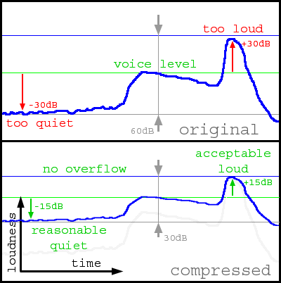
You should not use this option instead of player volume or system volume. An overflow and a noticeable decrease of playing quality can take place when there is a high gain. For more information, refer to 7.1. Loudness and dynamic range.
Master level defines the desirable gain level in dB. If the existing scale is insufficient, you can set the desirable gain level in the entry field without any restrictions.
Gain level reflects the current gain level. If there is no overflow then the Gain level coincides with the Master level. When an overflow takes place, the automatic gain control system decreases this level. Thus, changing of gain level can indicate too high Master level set.
Refer to Auto gain control and One-pass norm options of 6.3. Mixer settings section.
DRC Enabled checkbox switches dynamic range compression function. The first level defines compression level of the dynamic range. The second level reflects the current gain level. For more information, refer to 7.1. Loudness and dynamic range.
It displays type and parameters of the current audio stream. Input row reflects type of input stream. Text box displays the format information. Decoders for different formats display different information, including:
Frames/errors fields reflect the decoder statistics: number of decoded frames / number of error frames. There must be no errors in normal operating mode!
This indicator shows the usage of CPU resources by the filter.
Here the current input and output peak levels of signal are displayed. They are shown in a logarithmic form. When there is an overflow output level indicators become red. In this case, it is recommended to reduce gain (Gain level), since overflow means appearing of distortions (refer to 7.1. Loudness and dynamic range).
This page contains settings for mixing control.

The main element of this page is mixing matrix. It is represented in a form of matrix multiplication:

Simpler it means that there is a following rule for every cell: we mix the channel given by the column into the channel given by the row with gain given by the cell. Therefore, if we want to direct left channel into right channel we should set the value of cell on the cross of 'L' column and 'R' row as 1. Then we will hear both left and right channels from right channel.
It is necessary to clear the difference between input and output channels. Input channel is information that was encoded in original stream. Output channel is that of we will hear from speakers.
Matrix row defines the contents of output channel (speaker) given by this row. Therefore, the first row of the matrix above indicates sound, which will be heard from the left speaker:
L' = 1 * L + 0.7071 * C + 1 * SL + 1 * LFE
i.e. from the left speaker we will hear the left channel, part of the central channel, the left rear and the low frequency effects channel. Thus, mixing from 6 original channels into 2 stereo channels is performed (downmix).
One important property of matrix is that when swapping contents of two matrix rows we can 'interchange' appropriate speakers. Therefore, swapping of the first and the third rows results in 'interchange' between the left and right speakers. This property can be used to rearrange speakers without their physical switching.
Values of the matrix column show the target of the channel mixing. Therefore, the central channel is directed both to the left and right speakers with the 0.7 factor (otherwise the center outgoing from two speakers, will sound louder than if we would have the real third speaker). Thus, we will hear the central channel in the middle of the left and right speakers. Changing factor of the left or right channel you can 'move' the center. Thus, setting ' � ' column value of the 'L' row as 1 will result in louder sound effect of the center from the left channel. The center will seem to be moved to the left.
In most cases there�s no need to change the matrix manually: when the AutoMatrix option is on the mixing matrix is calculated automatically based on the following parameters: speakers mode, Voice, Surround, LFE levels, Normalize matrix, Voice control, Expand stereo options. Thus, level changing for the central (voice) channel will result in changes of matrix coefficients (column 'C').
Master/Gain - desirable and current gain level (refer to 6.2. Main settings ).
Voice - gain level of the center channel. If the input signal contains real central channel, then this level affects only on this channel. If there is no central channel but Voice control flag is set, this level controls the level of 'virtual' center. This level is a matrix parameter, so it makes sense only when the Auto matrix option is on. When changing level the matrix is recalculated.
Surround - rear gain level. If there are rear channels in input signal then this level affects only on them both in case of down mixing (in this case level of rear channels mixing into front channels is controlled) or without it (i.e. just control channel levels in respect of the frontal channels). If there are no rear channels in source but Expand stereo flag is set, then this level controls the level of 'virtual' rear. This level is a matrix parameter, so it makes sense only when the Auto matrix option is on. When changing level the matrix is recalculated.
LFE - LFE channel level. This level is a matrix parameter, so it makes sense only when the Auto matrix option is on. The matrix is recalculated when changing the level.
Matrix selection list allows to save and upload matrices.
This page contains gain level settings:

Master/Gain - desirable and current gain level (refer to 6.2. Main settings ).
DRC Enabled checkbox switches dynamic range compression function. The first level defines compression level of the dynamic range. The second level reflects current gain level. For more information, refer to 7.1. Loudness and dynamic range.
These are delays for each output channel. Delay values can be set in different units (Units selection list). Positive values for time units mean that positive delay will be introduced, i.e. the sound will be delayed. Conversely, positive values for distance units mean negative delay, i.e. the sound will be played 'in advance'. In both cases, there can be negative delay values. There are two main applications of delays:
Gain levels of input channels. Sometimes it is required to change gain levels namely of input channels. That's the case when the input signal has a central channel while the output one has no central channel (the center is mixed to front channels), and it is required to change dialog level namely. I.e. these levels are intended for record defects compensation.
Gain levels of output channels. These levels serve for speakers loudness equalization (if speakers are located asymmetrically). In other words, they serve for compensation of acoustic system defects.
This page reflects system settings (which have no direct influence on sound):

It defines the cases of AC3Filter use.
This setting defines formats supported by external decoder and being transferred without any modifications when digital output is used. It makes sense only if the SPDIF option is on (refer to 6.2. Main settings).
The filter is installed into the system with the highest priority, i.e. it will be used instead of any other decoders installed. If it is required to use other decoders by any reasons, the priority can be decreased to minimum using the Prefer other decoder option. Filter will stay in system and will be used only if there are no other decoders installed. Prefer AC3Filter option means the high priority.
Audio card can operate in two modes: DirectSound and WaveOut. If there are some problems occur when using the filter (e.g. SPDIF is inoperative), sometimes they can be solved by switching of operating mode. Some players have settings to change output device (refer to 5. Player setup), others use the default system settings. To switch the operating mode use Use DirectSound option for DirectSound interface, and Use WaveOut option for WaveOut interface. This option changes the system global settings! Thus, it is preferably to use native settings of player if possible.
This option takes effect only if the player uses the default output device or if it has appropriate settings.
In some cases, audio and video can be non-synchronized. Generally, this can occur due to incorrect mixing of video file, but the hardware causes of desynchronization are possible too. This option is intended to solve hardware problems. It can be used for defect correction of certain file, but do not forget to change it back! Here shift between audio and video is specified in ms. If sound is heard before video you should increase this value. If sound occurs after picture on the screen, you should decrease the value. This option helps to correct constant time shift only.
Option takes effect immediately. When changing the delay value the picture can freeze or jerk within several seconds.
Audio quality is a very complex concept depending on a huge number of factors and their relationship: type of acoustic system, listening conditions, quality of original record, listener himself, and many others. It is impossible to give some unique recommendations about how to reach good quality. There is no any unique formula and ideal sound: the record prepared for one listening conditions can sound absolutely unacceptable in other environment. However, we will try to present some of basic principles, which can help to understand what to do in each specific case. Therefore, it is strongly recommended to read this section for full understanding of filter abilities.
This question, which seems to be clear is hard enough to formalize, since different cases imply absolutely different things.
The sense of loudness is most clear when speaking about acoustic pressure, since that is directly perceived by ear.
Acoustic pressure is an additional pressure, which occurs when the acoustic wave passes through liquid or gaseous medium. When propagating through medium acoustic wave forms some compressions and depressions, which make additional variation of pressure with respect to average value of medium pressure. Thus, the acoustic pressure is a variable part of pressure, i.e. variation of pressure with respect to average value with frequency corresponding to acoustic wave frequency. (Great Soviet Encyclopedia)
Thus, we can measure any sound - loud sounds produce high pressure, quiet ones produce low pressure. The pressure is measured in Pascals, however, in acoustics it is usually measured in decibels (dB) with respect to the hearing threshold. By definition, the value of hearing threshold is accepted to pt = 0.00002 Pa = 20 mkPa. The hearing threshold is taken as 0 dB and loudness is calculated as l = 20 * log(p / pt), where l [dB] is loudness (in terms of acoustic pressure), p [Pa] is acoustic pressure, pt [Pa] is hearing threshold. At the same time, all audible sounds have positive loudness value; all inaudible sounds (below the hearing threshold) have negative value; loudness change by 6 dB corresponds to the double change in pressure; change by 20 dB corresponds to the tenfold change in pressure. Loudness in terms of acoustic pressure we will call an absolute loudness.
Here are some typical loudness values:
| Sound | Loudness | Pressure |
| Hearing threshold | 0dB | 20 mkPa |
| Rustling of leaves and gentle breeze Wristwatch ticking Breath |
10-20dB | 60 - 200 mPa |
| Quiet whisper Clock ticking |
20-30dB | 200 - 600 mPa |
| Noise indoors | 30-40dB | 0.6 - 2 mPa |
| Quiet conversation | 40-50dB | 2 - 6 mPa |
| Normal conversation | 50-60dB | 6 - 20 mPa |
| Loud conversation | 60-70dB | 20 - 60 mPa |
| Noisy street | 70-80dB | 60 - 200 mPa |
| Noise of the truck engine | ~80dB | 200 mPa |
| Underground railroad noise on the run Chisel hammer |
~90dB | 600 mPa |
| Loud disco | 100-120dB | 2 - 20 Pa |
| Plane taking-off | 120dB | 20 Pa |
| Pain threshold | 130dB | 60 Pa |
Note the perceived pressure range: hearing threshold pressure and pressure produced by plane differ in million times! Therefore, the logarithmic scale is in a better accordance with the ear physiology - the linear change of acoustic pressure does not correspond with sense of loudness linear change. For instance, change of acoustic pressure by 50 mPa during conversation will be extremely sensible; however, it will be absolutely insensible during plane taking-off. But change of acoustic pressure by 6 dB (in twice) will be perceived as an approximately equal loudness change in both cases, though in the first case it will correspond to change of pressure by 25 mPa, and in second case - by 10 Pa.
Another type of loudness is a record loudness (signal loudness). This loudness is not an acoustic pressure (it can be voltage, magnetic polarization, etc.), however acoustic pressure is produced by acoustic system in accordance with loudness of recorded signal. Each certain signal loudness corresponds to the certain acoustic pressure. Signal loudness can also be measured in decibels. However, while the acoustic pressure is usually measured with respect to hearing threshold (minimum audible acoustic pressure), loudness of digital signal is usually measured with respect to maximum digital level accepted as 0 dB. Thus, loudness of digital signal is represented by negative values (-3 dB, -20 dB) since the record loudness must always be lower than the maximum one. The lower loudness value, the quieter the signal (-20 dB is quieter than -3 dB). Positive loudness of the digital signal means overflow and results in appearance of digital distortions. (These distortions will be considered later).
Volume controls of amplifier, in system settings, of player do not produce any acoustic pressure at all. Without signal even at maximum volume settings, we will hear nothing (with the assumption that the playing system does not produce any noise). Therefore, these settings affect loudness indirectly only and have sense of signal gain. (The gain may mean the signal decay too). From here, we will not use the term of loudness for gain levels notation except system loudness since this is established term. We will consider gain level set both in operating system settings and in player, amplifier/receiver, etc. as system loudness.
Gain level can also be measured in decibels. It is convenient since in this case the signal loudness and the gain level are simply summed. For instance, signal with loudness of 70 dB gained by 10 dB will sound with loudness of 80 dB. However though loudness and the gain are measured in same units you should distinguish them.
During playing, the recorded signal is converted into acoustic pressure using acoustic system. Let the maximum pressure produced by acoustic system is 100 dB. Then the record with loudness of 0 dB will produce pressure of 100 dB, the record with loudness of - 30 dB will produce pressure of 70 dB, etc. When changing the gain level the absolute loudness will change too. Therefore, when changing the gain level you can always set up a correspondence between the record loudness and the required absolute loudness. For instance, if the conversation level in movie is -30 dB and we want to hear these dialogues with natural loudness, the record loudness must correspond to the pressure of 50 dB. Since when the gain level is maximum (0 dB) the record level of -30 dB produces pressure of 70 dB (too high), while when the level is -20 dB the same record loudness produces the required 50 dB of pressure. Acoustic system adjusted in such way is called calibrated, i.e. the calibrated acoustic system is a system with sounds with the correct absolute loudness produced. (In fact, the calibrating process can be much more complex and can include much more parameters, however here and further we will talk about loudness calibrating only). Most of household devices have no labels of the gain level control (or there can be some abstract percents or other meaningless characters), therefore, it is difficult for user to make a precise calibration of acoustic system.
Hearing adaptation also affects loudness perception. Hearing adapts to loudness of surrounding noise and corrects loudness perception accordingly. Certainly, you could see that the man with earphones where loud music is playing begins to talk louder (with point of perception of people around him), however with his point of view it is normal speech loudness (with respect to loudness of earphones sound). Otherwise, in full silence, people begin to whisper and nevertheless it seems to be loud. In conditions of normal city noise, it is difficult to hear ticking of mechanical watches - this sound is perceived as very quiet. But the same watch ticking in full silence at night can be perceived as clear heard sound. Thus, the third type of loudness appears - subjective loudness. We will not discuss some kinds of subjective loudness measuring, just talk about qualitative comparing of sounds (louder-quieter).
Thus, sound with the same absolute loudness can be perceived as loud or quiet depending on the environment. Assume that we have adjusted the gain level so as the dialogue loudness in the movie approximately corresponds to reality. So if there is a sound of watch ticking in silence in the movie then we will not hear this sound at all when watching the movie since it is significantly quieter then the surrounding noise and our hearing is adapted to eliminate the surrounding noise. In good hearing conditions when there is no surrounding noise the same watches will be heard clearly.
In most cases, it is convenient to measure record loudness with respect to some reference level. For instance, if the record loudness is -20 dB, is it loud or quiet? And if we know that the dialogue loudness in the same record is -30 dB we can just say that it is loud enough, and if dialogue loudness is -10 dB, we can say that it is quiet enough. Dialogue level (average loudness of the conversation) is a very convenient reference level, which can be used for orienting. If sound loudness of 10 dB is higher than the dialogue level then it is loud, and if loudness of 10 dB is lower than the dialogue level then it is quiet. At the same time the dialogue level can be arbitrary and depend on the record - one record may have dialogue level of -10 dB, and the other one may have dialogue level of -30 dB. Anyway, all sounds with loudness which is lower than the dialogue level will be perceived like quiet sounds, while ones with loudness which is higher than the dialogue level will be perceived like the loud sounds, even if the system have been calibrated incorrectly, and dialogues will sound with absolute loudness of 40 dB or 60 dB. Due to the property of adaptation, hearing adapts to the current average loudness and introduces an appropriate 'correction'. However, the correct perception of loudness will be broken when loudness of surrounding noise is approaching dialogue loudness (or even exceeds it). In such a case, all sounds played will seem to be quiet.
Thus, we can introduce one more loudness scale (in addition to the digital signal loudness scale and the absolute loudness scale) - loudness with respect to the dialogue level. When comparing different loudness we will get the follows:
| Absolute loudness of real sounds | Loudness with respect to the dialogue level | Record level-1 | Record level-2 | Absolute loudness during record playing 1 | Absolute loudness during record playing 2 | |
| Quiet sounds | ||||||
| Quiet whisper | 10dB | -40dB | -70dB | -50dB | 10dB | 10dB |
| Noise norm in living quarters | 20..30dB | -20..-30dB | -50..-60dB | -30..-40dB | 20..30dB | 20..30dB |
| Quiet conversation | 40dB | -10dB | -40dB | -20dB | 40dB | 40dB |
| Dialogue level | ||||||
| Normal conversation | 50dB | 0dB | -30dB | -10dB | 50dB | 50dB |
| Loud sounds | ||||||
| Noise of a typewriter | 70dB | +20dB | -10dB | 0dB (maximum) | 70dB | 60dB |
| Noise of truck engine working | 80dB | +30dB | 0dB (maximum) | 0dB | 80dB | 60dB |
| Loud horn within at a distance of 5-7 m | 100dB | +50dB | 0dB | 0dB | 80dB | 60dB |
| Noise of a tractor working at a distance of 1 m | 120dB | +70dB | 0dB | 0dB | 80dB | 60dB |
| Pain threshold | 130dB | +80dB | 0dB | 0dB | 80dB | 60dB |
There are also two hypothetical records made in different environments given in the table: dialogue level of record-1 is -30 dB while that of record-2 is -10 dB. It is clear that when playing on calibrated system the first record transfers loud sounds much better - it is possible to reproduce sounds with loudness up to 80 dB, while the second record reproduces sounds with loudness up to 60 db only.
Note that two mentioned records require different calibration of acoustic system. Thus, for acoustics that is able to produce 100 dB pressure the gain level required for the first record is -20 dB, and that required for the second record is -40 dB. Hence, the first record requires significantly higher gain and the first record will sound significantly quieter when the gain level settings are equal. Therefore, the second record is suitable for non-calibrated systems since it allows strong deviations of the gain level.
Thus, record-1 transfers loud sounds well but requires higher gain level; if there is an insufficient gain or some external noise this record will be perceived like extremely quiet. Record-2 does not require high gain, it is heard well even if the gain levels are low or some noise exists, but this record cannot transfer loud sounds well.
And now let's remember that audio signal is alternating:
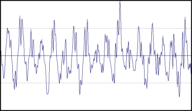
What is required for loudness evaluation? Obviously, variation of pressure for one period of acoustic wave has no sense of sound loudness change since we cannot hear single oscillation. Therefore, we must find loudness within the certain time interval but not for one point. There are many different methods for loudness evaluation. The simplest one is to find the maximum and to calculate the signal energy. More complex methods take into account the non-uniformity of hearing of sounds of different frequency and intensity.
When finding loudness as maximum of the signal we scan the range looking for signal maximum:
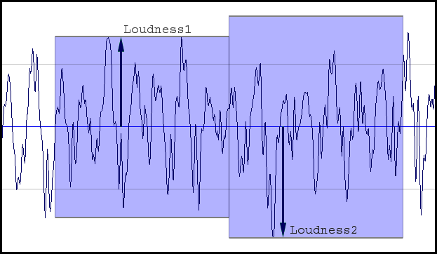
The found level in dB will define loudness. To distinguish this loudness from ones obtained by other methods it is called the peak level. From here, we will use only this loudness definition. In fact, this definition does not reflect the real loudness perception well but it is convenient for the next discussion, therefore we will not consider in details any other methods of loudness evaluation even if they are more precise.
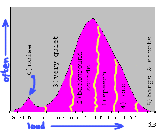
This picture illustrates loudness distribution of typical DVD movie (DVD FightClub, hereinafter we will consider only original audio tracks with no transformation and no mixing in order not to distort sound pattern). X axis reflects loudness in decibels, Y-axis reflects occurrence rate of sound of this loudness. It is better to say that during the movie playing the current loudness have been continuously controlled. The more often a loudness occurred during the movie playing the higher the histogram of this part. I.e. we can say that there are few explosions in the movie but at the same time, there are many different background sounds. The histogram is divided into the several conventional areas:
Boundaries between areas are rather conventional and can be modified for different records. In this case, it is known that the dialogue level is -27 dB.
Looking at the histogram, we can note some interesting moments. Firstly, the most often sounds in the movie were the ones with loudness of -40 dB. Let us just note this fact for now. Secondly, the main hump of histogram is located in area from 0 dB (maximum level) to -70 dB (minimum level). It is reasonable to assume that all significant sounds are inside of this hump while the quieter sounds are just a noise. This value is called dynamic range and will be very important further.
This situation is typical enough for DVD movies. Dialogues take much time; background sounds and music take a little more time; some loudness surges occur periodically with the following decays. Generally, sound pattern of this movie is balanced enough and practically full available dynamical range is used.
Let�s look at some other movies:
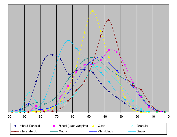
These examples can be divided into two large groups. First group is characterized by almost full absence of loud sounds (Cube, Dracula, About Schmidt, Savior). Loudness range from 0 dB to -15 dB (very loud sounds) is not practically used here. Otherwise, loud sounds are extremely important for the second group of movies (Interstate60, Blood (Last Vampire), Pitch Black, Matrix). It seems that the number of these sounds is relatively small and they play no special role. However, for instance, the sound of a shot has duration of a split second (the louder part) but exactly high loudness accentuates this sound. If this sound was quieter there would be an effect of �flatness� and inexpressiveness of the sound. Even when occurring once during the movie loud sound has no great sense in movies of the first type ('quiet' movies); therefore its loudness is not critical so much. Otherwise, in movies of the second type those sounds (even with the small duration) form the mood of the movie.
Another conspicuous feature - high 'humps' in Cube and Interstate 60 movies. There is a constant quiet background hum in the Cube movie. This is why the graph has 'hump' at loudness of approximately -50 dB. The same thing relates to the Interstate 60 movie - it is car travel and, consequently, there is a constant sound of moving car. Shapes of both histograms are very similar; however, the maximum of the histogram for the Interstate 60 movie is lower by 10 dB. As the voice levels are the same in both movies, one can immediately conclude that sound in the Cube movie is much quieter. This conclusion is far from an obvious one. Let us recall hearing adaptation - if we shift graphs to align their maximums at one level, the Cube movie will be perceived as 'quiet' all the same.
The other movies have no such well-marked background sounds, so their graphs are more distributed across the dynamic range.
About Schmidt movie has 'hump' at the level of -70 dB - -80 dB. These are recor ding noises; and they are relatively loud in this movie, as compared with other movies, but quiet enough and do not hinder viewing.
So far, we considered solely movies. Now let us have a look at music:
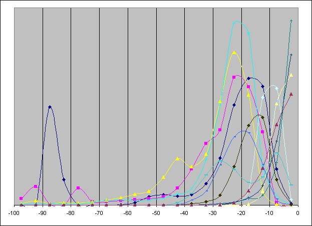
Right off, it strikes the eye that distribution of loudness is absolutely different. ( To show a variety, there are histograms of various music styles having different quality collected. They do not show a real balance of different types of compositions .) All sounds are very much shifted towards the 'loud' part of the dynamic range. The difference between middle-level loudness of movies reaches 40 dB. Besides, a characteristic feature of the movies is a smooth decrease of the histogram in the loud area, whereas for music a histogram maximum often reaches the highest level (0 dB). A small number of such graphs is provided; nevertheless, such situation is very widespread.
The dialogue level concept is often inapplicable to music, thus it is very difficult to separate loud and quiet sounds. Therefore, it is also difficult to determine a subjective loudness of a composition. So, a subjectively loud composition may be objectively quieter than a subjectively loud one. Positive or negative drops of the loudness have a great importance here; these drops are not visible on the histograms.
Absence of a common reference mark results in a chaos - sounds from different sources have different loudness; difference between maximums of composition histograms reaches 20 dB. Besides, in general it is very difficult to formalize a concept of a 'composition's loudness' anyhow. Certainly, many people are familiar with a situation when there is a variety of music from different sources and during its successive playback (e.g., if music is recorded on an audio CD), loudness changes at every passing from one composition to another. It is unpleasant (the mentioned effect of a mismatch between actual loudness and subjective loudness may more embarrass a perception). The provided graphs illustrate this situation very well.
Dynamic range of musical compositions (difference between the loudest and the quietest sounds) is 20-40 dB that is far less than dynamic range (70 dB) of movies.
The average loudness level of musical records (as well as of Windows system sounds) is notably higher than a loudness of DVD movies. Therefore, under the same settings of the system loudness the absolute loudness of movies will be significantly lower. In the presence of external noises loudness may turn out to be insufficient, hearing will be poor (sic!) and it will seem that the sound is of a poor quality. Gain increase in system settings and in amplifier, even to a maximum, may fail to resolve the problem: difference of average loudness reaches 40 dB; it is too high. However, even if an amplifier's power turns out to be sufficient and a DVD is played with sufficient absolute loudness it is not always suitable, as sounds of operating system, which have normal absolute loudness under normal gain settings, will be simply thundering.
This problem is typical mainly for computer playback, as in hardware players gain level is controlled by the decoder itself. Some program DVD players are able to control the system loudness, but it is not always suitable, as in this case loudness of all system sounds will be changed (you may accidentally deafen your neighbors). Besides, in any case, the program cannot control loudness at an external amplifier. So, it is just a partial solution of the problem.
A compromise solution is to process the sound immediately before playback. Such processing can greatly enhance quality of certain record playback under certain conditions. Many people may object that in doing so 'quality' will be lost; however, as it has been already mentioned, there is no absolute quality. We do not set ourselves a goal to cue the sound; our goal is to ensure a pleasant listening to it under our conditions. If an acoustic system does not have sufficient power or if you have nervous neighbors it will be just unpleasant to view a movie with lowered loudness when you cannot distinguish a half of words and a half of quiet sounds is not heard. Even self-suggestion that maximum quality is achieved will not smooth this impression. I should repeat once more the key idea: quality is estimated by our ears . The sound passes many processing stages before it reaches a listener, and a variety of acoustic devices and their characteristics is so wide that the last processing stage before playback is actually a necessity.
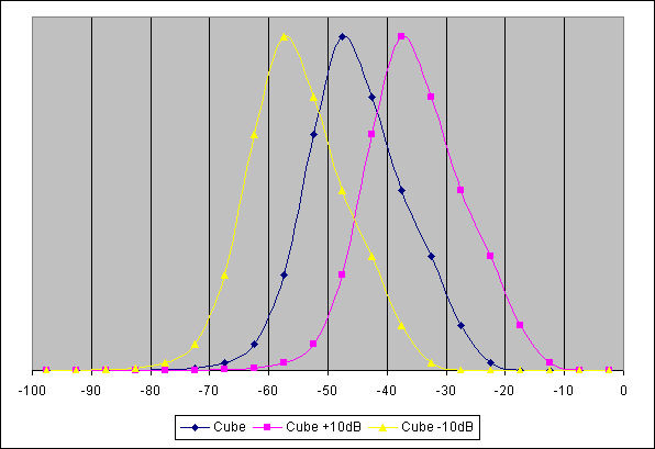
Level change is simply multiplication of signal amplitude by a defined value. It results in a change (increase or decrease) of the entire signal loudness.
Logarithmically, multiplication by a number is just an addition of a constant. So, if the same number is added to all levels the levels' histogram will be simply shifted:
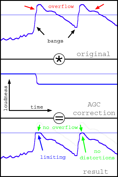
If we multiply the signal by a too big number, it may result in an overflow. If an overflow is not tracked the amplitude will be equal to virtually random values (see the figure), and this results in frequent clicks, which are very noticeable audibly. The easiest way to struggle with this defect is clipping. That is, a signal is clipped when its amplitude goes beyond limits (see the figure). If the overflow is small, the clipping is almost imperceptible audibly; however, when the level increased clipping is heard in the sound as 'sand'.
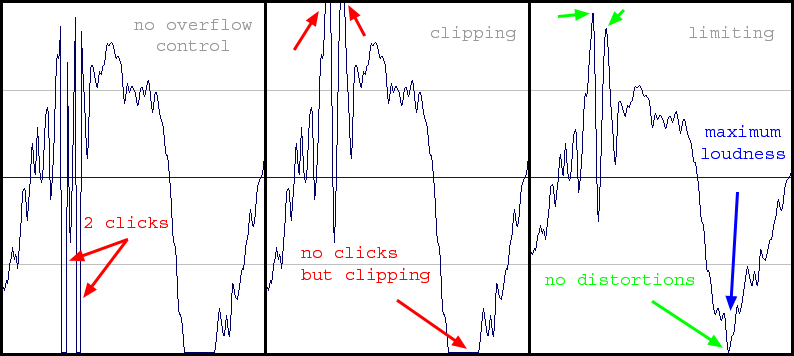
More complicated, but more efficient way is limiting. It consists in an automatic decrease of the signal level to prevent overflow. To do this, it is necessary to use automatic gain control (AGC), which will adjust t he current signal level. Thus, when there is no overflowing AGS does not change a signal, and as soon as a signal exceeds the maximum level, adjustment is made, which changes the signal to make its level lower than the maximum one. As it can be seen on the figure, the signal completely preserves its form! However, at that loudness remains at maximum.
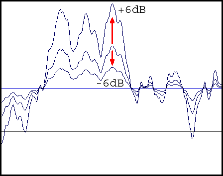
It is necessary to take into account that the previous picture shows amplitude and this one shows loudness (defined on the basis of a large group of amplitudes). Therefore, notwithstanding that loudness graph is 'cut off', the form of the signal itself is distorted in minimum. This way is not free from shortcomings also. Initially, loudness of the signal itself varied, and after the limitation, all sounds that go beyond the limits have the same loudness. As a result, the sound may become 'flat' and inexpressive. Let us look at histograms (Fight Club):
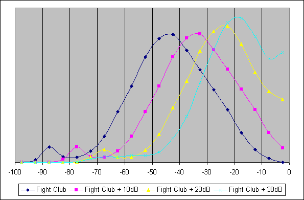
An example of unsuccessful gain is shown here. With gain of +10 dB, distortions are still less noticeable (there is still a relatively small number of scenes in the movie where overflow takes place). However, with an increase of gain, the level is limited more and more often, and when the level is equal to +30 dB voice begins to be limited that is highly noticeable. Shortcomings of the limitation are especially noticeable when loudness changes significantly over a short time period - subjectively, loudness begins to jump up and down. If, against a background conversation (which, at the gain of +30 dB, is already reproduced with maximum loudness), loud sound is heard (which is louder than the voice in the original, e.g. a telephone ring) the gain level is decreased to prevent distortion of loud sound, but at that the conversation loudness drops abruptly, too. When the loud sound ceases, the conversation loudness returns to the original level, abruptly as well:
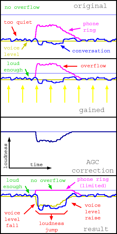
Thus, relative loudness of various sounds reproduced simultaneously is preserved, but gain level is continuously varying. It is well noticeable and very unpleasant. Thus, at high gain levels (20-30 dB and more) the limitation also produces a bad result.
When gain levels are small, the signal limitation defects are practically unnoticeable, whereas the signal clipping is heard well virtually always. That is, under otherwise equal conditions, limitation gives more good result. The filter always performs either limitation (the AGC option is switched on) or clipping (the AGC option is switched off). Hereafter, unless otherwise specified explicitly, it will be assumed that the limitation is switched on. Thus, it is recommended to keep the AGC option active.
Let us set a goal to raise loudness without any loss of quality at all. Is it possible? Yes, if there is a 'margin' of the dynamic range. Let us look again at movies' histograms, Cube movie in particular (the yellow graph). One can see on the histogram that loudness does not rise higher than -15 dB (it is possible that in the entire movie there are one-two such occasions; however, for the purposes of this review we will assume that there are no loud sounds at all). So, as there are no loud sounds, it is possible to raise loudness by 15 dB without loss of quality!
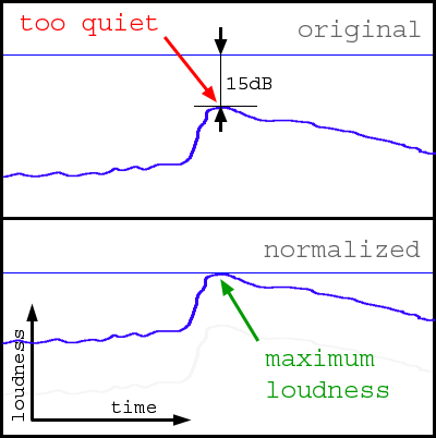
Except for increase of loudness, there are no other changes in the signal. At that, the histogram will shift close by the right-hand margin without changing a form:
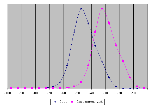
Thus, it will turn out that there is now a sound in the movie having maximum loudness. However, if we continue to increase loudness the distortions (described above) will appear. Such signal form where there is a sound of maximum loudness without introduced distortions is called normalized and the process is called normalization. Normalization is often carried out at the musical records preparation stage, and the sound reaches us already normalized (e.g. AudioCD). However, the normalization is not carried out for movies. Why?
Let us recall histograms for music and a chaos relating to loudness. For music, it is important to playback with maximum loudness, as it is meant for maximum target audience - CD players, a noisy street, underground, cheap earphones, croaky radio stations where low sounds less than -40 dB are not hearable. (Let us have a one more look at graphs for music - minimum loudness is approximately equal to - 40 dB.)
For DVD it is not so. They are primarily designed for quality home cinema. Playback equipment should be calibrated to reproduce dialogs always with the same absolute loudness for any movie, will it be an action movie with explosions smashing a wall or a melodrama with soft rustle of grass. At that, playback system should always be ready to playback these sounds without necessity to change the gain level manually. Thus, the most important is not a necessity to make a record maximum loud, but a necessity to have fixed reference level to make it possible for a decoder to adjust gain level automatically. This reference level may be any (as a matter of fact, this is not important, i.e. if there is a reference level, corresponding adjustment may be made at any time). The standard de facto for DVD is the dialog level equal to -27 dB. Thus, even if a movie does not contain loud sounds, one should not carry out normalization at the disc creation stage and the dynamic range remains unspent.
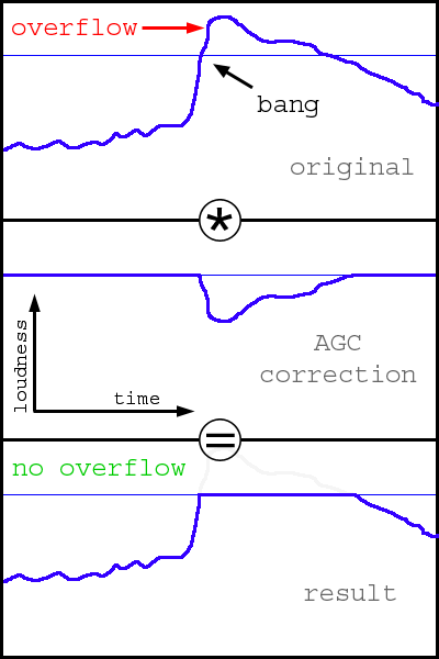
So, for the purpose of loudness increasing normalization is useful. However, to carry out normalization, one needs to know maximum recording level. To identify it, one needs to review the whole record beforehand. However, it is not always possible and is inconvenient. There is a normalization method, which does not need preview of the whole record - the one-pass normalization. The method consists in a constant search for maximum when we are watching a movie. At the initial moment, the gain is at maximum. When an overflow arises, we decrease gain:
As it shown on the figure, the first loudness peak is clipped almost in the same way as in the case of usual overflow, but duration of 'clipping' is significantly shorter (compare with simple limitating) and later there will be no overflows. Thus, gain will be adjusted when every new maximum is found, and, as a result, the histogram is automatically shifted to achieve maximum loudness.
As all other, the method is not free from shortcomings. First, the method introduces distortions (though they are low observable, it is necessary to know precisely what to listen to in order to notice the one-pass normalization). Second, loudness is continuously decreasing during a movie show (though usually the main loudness decrease process ends during the first 10-15 minutes of a movie and so it is practically unnoticeable). And third, it may be that the main goal (loudness increase) will not be achieved - everything depends upon the movie itself (it relates also to the usual normalization). Here is an example of histograms obtained in the case of one-pass normalization of the Cube (where normalization is possible) and Fight Club (where normalization will not give the desirable effect) movies:
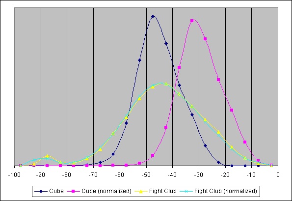
As it seen on these histograms, the result is drastically different. Activation of one-pass normalization gives a substantial positive effect for the Cube movie - sound has become noticeably louder (our assumption that sounds louder than -15 dB are absent in the movie was confirmed - compare with normalization graph). However, in the Fight Club movie no increase of loudness took place at all - thus the desired effect was not achieved, but additional distortions were introduced.
It is necessary to note once more that for one-pass normalization operation preliminary (initial) gain is needed - without level rising, the one-way normalization is senseless. As well as the normal gain, it is set by the Master level. However, if it is too strong loudness drop from the beginning of the algorithm operation will be very noticeable.
Let us think: what for do we need to raise loudness? Is it needed in order to hear quiet sounds, which are inaudible in our circumstances (e.g., if it is impossible to listen loud sounds, if there are unwanted noises in the room, etc.)? Is it possible to amplify quiet sounds without processing loud sounds? It turns out that it is possible. This technique is called the Dynamic Range Compression (DRC). For this compression, it is necessary to change the current loudness constantly: to amplify quiet sounds and not to amplify loud ones. The simplest law of loudness change is linear, i.e. loudness is changed according to the law: output_loudness = k * input_loudness, where k - dynamic range compression coefficient:
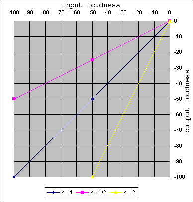
When k = 1, no changes are made (output loudness is equal to input one). When k < 1, loudness will increase and the dynamic range will be contracted. Let us have a look at the graph (k=1/2) - quiet sound with loudness equal to -50 dB will be higher by 25 dB, that is significantly louder. Meanwhile dialog loudness (-27 dB) will rise only by 13.5 dB, and loudness of the loudest sounds (0 dB) will not change at all. When k > 1, loudness will decrease and the dynamic range will increase.
Let us look at loudness graphs (k = 1/2: the dynamic range will be compressed in double):
As it may be seen, there were very quiet sounds in the original that were lower than dialog level by 30 dB, as well as very loud ones higher than dialog level by 30 dB. Thus, the dynamic range is 60 dB. After compression, loud sounds are higher just by 15 dB, and quiet ones are lower than dialog level by 15 dB (the dynamic range is now equal to 30 dB). Thus, loud sounds have become significantly quieter, and quiet sounds - significantly louder. At that, there is no overflow!
Let us now consider histograms:
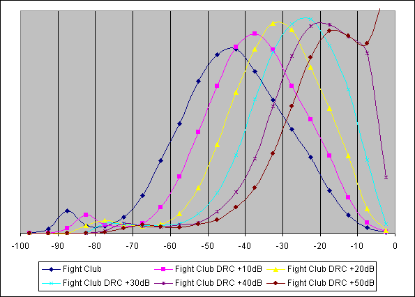
As it clearly seen, when gain level is up to +30 dB the histogram form is well preserved. It means that loud sounds remain well marked (they do not become maximum and are not clipped as in the process of simple gain). At that, quiet sounds are identified. The histogram shows it poorly but the difference is very noticeable by ears. The method's shortcoming: the same jumps of loudness. However, their generation mechanism differs from jumps of loudness arising during clipping, and their character is completely different: they arise generally in the case of very high gain of quiet sounds (and not during clipping of loud sounds as in the process of the normal gain). Excessive compression level results in flattening of the sound pattern: all sounds tend to be equally loud and inexpressive.
High gain of quiet sounds may result in audible recording noise. Thus, the filter uses a somewhat modified algorithm to lessen an increase of noise level:
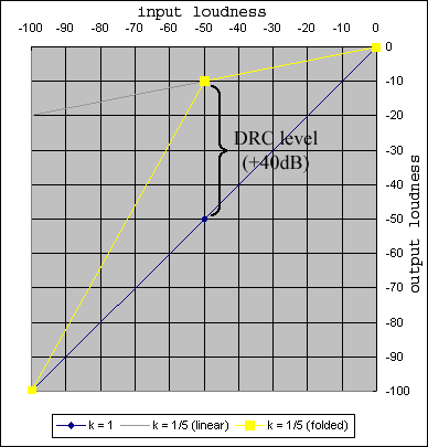
That is, at loudness level equal to -50 dB there is a knee of the transfer function and noises will be amplified less (yellow line). When there is no such knee, noises will be significantly louder (grey line). Such simple modification significantly decreases noise level even at very high compression levels (on the figure - compression is equal to 1.5). The DRC level of the filter defines gain level for quiet sounds (-50 dB), thus the compression level 1/5 shown on the figure corresponds to +40 dB level in filter settings.
There is one more detail not obvious, which may highly influence loudness during playback of multichannel records on a stereo system (or using headphones). Let us suppose that we have an initial record in the 5.1 format and it is necessary to obtain two channels at the output. Into each output channel there are mixed: one front channel, one rear channel, the LFE channel and part of the central channel:
L' = L + 0.7*C + SL + LFELet us suppose that there is maximum loud sound simultaneously in all input channels (though it is not probable enough). Then the amplitude in the output channel will be 3.7 times more than maximum (by 11 dB), i.e. there will be the highest overflow. To prevent overflow, mixing formulas should be rewritten in the following way:
L' = (L + 0.7*C + SL + LFE) / 3.7This is a normalized mixing (you should not confuse it with normalization of record itself) - this guarantees absence of an overflow. However, sound mixed in this way is quieter by 11 dB! Is it possible not to carry out normalization? Yes. However, in this case there are possible overflow and related distortions. Overflow arises only then when all input channels simultaneously reproduce a loud sound. It is not typical for movies (usually rear channels are noticeably quieter than front ones and the LFE channel is used far from always), but it is usual for multichannel musical records. That is why one may leave the non-normalized mixing for musical records, and for music, it is better to switch the normalization on. (In the filter, normalization of mixing is controlled by the Normalize matrix option).
Setting recommendations are highly depend on specific conditions of listening and a goal set. Conditionally, all conditions may be categorized as follows:
The best results may be achieved only by combining all methods. In this section, we will consider only a case of viewing DVD movies. For other cases (music, MPEG4 movies, etc.) sound characteristics are very different. However, after familiarization with the filter's setting for DVD-movies it is not difficult to study other cases.
Gain (Master level). Jumps of loudness arising in the case of overflow are unnoticeable only then when the sound being clipped is much louder than the basic one: in the example, relating to a telephone ring loudness of the telephone sound is comparable with loudness of voice sound. However, if instead of a telephone there will be a thundering explosion, voice sound will be indistinguishable in any case. Therefore, a limitation of the loudest sounds is admissible and practically unnoticeable. As very loud one may consider sounds from +15...+20 dB as related to dialog level. Thus, when dialog level is equal to -27 dB (de facto for DVD), the admissible gain level is equal to +7...+12 dB. As one more reference, one may address gain histograms: gain up to +10 dB does not highly influence the histogram form, while at gain equal to +20 dB a very large number of sounds will be limited. Thus, one may consider gain up to +10 dB as admissible. This value may be kept practically always: in movies with quiet sound, it will notably raise loudness, and in loud ones, it will not hinder very much. (We should note once more that the reasoning is provided only for the case of watching DVD movies; for music and for most mpeg4 movies it is inapplicable, as histograms' characteristics are very different).
Gain can also be used for limiting signal loudness (e.g. for listening at night). When dialog levels are equal to -27 dB and gain is equal to +17 dB dialog levels after gain will be equal to -10 dB, and level of the loudest sound will be equal, as usual, to 0 dB that is just by +10 dB higher than dialog level. Thus, setting gain in the filter equal to +17 dB and adjusting the system loudness so that dialogs will be reproduced with acceptable absolute loudness, we will get a guarantee that the loudest sounds will not exceed dialog levels by more than 10 dB (though, certainly, in this case signal limitation will be used for loud sounds).
Dynamic range compression (DRC). It is much more difficult to determine bounds of using compression, as audibility of compression defects is highly dependable on acoustic system, listening conditions and the listener him(her)self. If histograms are used to solve this issue the upper limit of compression applicability may be estimated as +20...+30 dB (see histograms). In this case, loud sounds still remain distinguished from quiet ones by loudness. Thus, compression level is selected only audibly, until the necessary loudness is achieved and defects will remain unnoticeable.
It is necessary to take into account that compression and gain are applied simultaneously. Thus, when the gain level is +20 dB and compression is twofold (+25 dB) the actual gain level will be equal to +10 dB. It is normal, as a requirement for gain is also decreased with an increase of compression.
One-pass normalization. It is also applicable practically always. For high-quality systems with low gain level it will allow to diminish number of overflows; and in other cases, combined with compression, it will allow to achieve maximum loudness, also with minimum of distortions related to overflow. An initial gain level (Master level) for normalization is selected on the basis of goals; if a high gain is not needed the desirable gain is set. To achieve maximum loudness, one may set a level equal to +20 dB.
The first that should be noted: LFE is not the same as a subwoofer! In addition, the designation '5.1' for AC3 does not coincide with '5.1' for an acoustic system. Thus, let us begin from considering this difference.
The AC3 format was created for cinema and not at all for a computer. At cinemas, quality acoustics may reproduce low frequencies quite adequately, whereas LFE was designed as a channel for powerful low-frequency effects that is effects, with which usual acoustics cannot cope any more. It is used in order to make walls to shake, people to cry from a horror and weak-nerved young ladies to faint. Thus, all channels of the ac-3 stream contain low frequencies and only sometime (in especially explosive moments) the LFE channel begins to operate, just to help the basic acoustics to shake wal ls. It may quite happen so that the LFE channel will never be switched on during the entire movie. This also will be normal.
The computer acoustics has quite another specific character. Most of contemporary 5.1 acoustics just is not able to reproduce low frequency through main speakers (satellites) and subwoofer should be entirely responsible for its reproduction. Thus, if we connect 5.1 acoustics and begin to watch movie with sound track of the 5.1 format assigning the LFE channel to the subwoofer (without redirection of low frequencies from main channels) we risk not to hear low frequencies at all!
Acoustic systems with subwoofer may be divided into several categories. First, an acoustic system may have a subwoofer, and, however, not have separate input for it. In this case, the acoustic system itself separates input signal into low-frequency signal for the subwoofer and signal for main speakers. It is necessary for such systems that all low-frequency information is already contained in the signal for main speakers, i.e. it is necessary to mix the LFE channel into all main channels. Thus, output mode should be indicated without subwoofer. (From the point of view of operating system and sound card, the acoustic system has no subwoofer, as the acoustic system has no separate input for it).
Systems where subwoofer is controlled separately may be divided into two categories.
To obtain more detailed information on purposes of channels, subwoofer and bass control, address the Dolby site: http://www.dolby.com/tech/c.in.0011.LFE.pdf (Eng).
SPDIF (S/P DIF, Sony/Philips Digital Interface, IEC958 "Digital audio interface" standard) is digital interface for sound transfer.
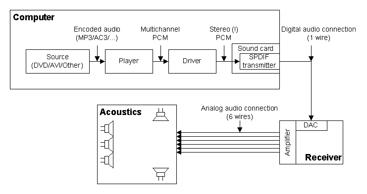
When the connection is analog, an acoustic system is connected in the following way:
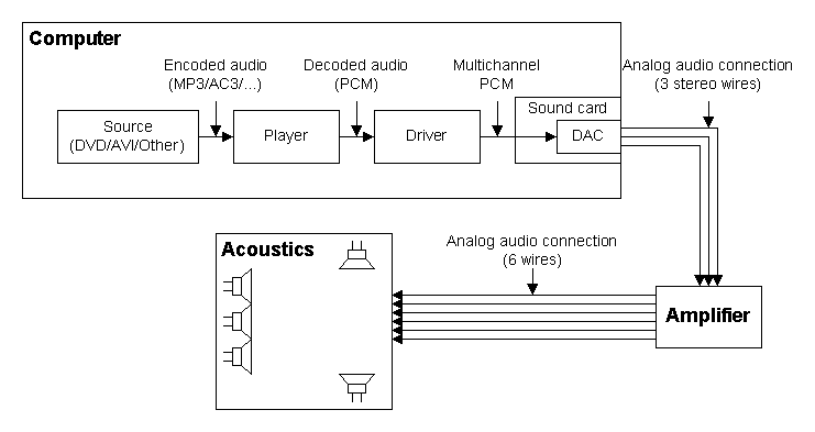
Digital-to-analog converter (DAC) is situated on the sound card, and sound is transferred out of computer in the analog form. For connection, one needs three stereo wires (for 6-channel system) from sound card to amplifier and six wires from amplifier to each speaker.
When the connection is digital the following connection scheme is us ed:
Here, to connect a receiver, only one wire is needed, and sound is transferred in digital form. DAC and amplifier are situated in the receiver. As DAC is subjected to lesser influence of electronic noises outside computer, and amplifier is situated nearby, the receiver can provide better sound quality in the digital transfer mode.
Initially, the SPDIF standard enabled transmission only of uncompressed PCM audio in stereo mode. However, as the transfer is made in digital form, one may transfer data of any format, if only transmission rate is satisfactory. So, the standard for transferring of compressed multichannel audio is SPDIF-passthrough mode. (A multichannel sound cannot be transmitted in uncompressed mode, as the transmission rate is limited.)
The pass-through communication mode may be illustrated in the following way:
Thus, sound is transmitted unchanged through the entire system from DVD disc (or other sound source) to receiver; it explains the mode's name. As the data are transferred without changes, other computer sound processing options, including change of loudness, are unavailable. All settings may be made for receiver only. Besides, at the same time only one sound source may be reproduced, as mixing of compressed sound is impossible.
As sound is transmitted in compressed form, receiver should be able to decode it. There are many sound compression formats, and it is obvious that receiver cannot support all existing formats. So the following formats are supported: AC3 (DolbyDigital), DTS, MPEG Audio (including MP3). However, not all receivers support even this set of formats, usually the AC3 is supported, rarely - the DTS format and more rarely - the MPEG Audio format. The DTS format ensures higher quality of sound, but the AC4 format is more widespread, as it is the standard for DVD.
As a decoder, a digital-to-analog converter and an amplifier are in the same device, it is possible to adjust the gain level automatically. It eliminates loudness problem.
To use the pass-through transfer mode there are necessary:
However, even when all these requirements are met the pass-through transfer mode may be used far from always. E.g., the SPDIF standard allows to use just three sampling rate: 48 kHz (DVD), 44.1 kHz (AudioCD) and 32 kHz. If the source has another sampling rate, the pass-through transfer is impossible. Besides, some sound cards (e.g. Creative) support only 48 kHz frequency, i.e. the mode may be used for DVD only and cannot be used with many other sources.
Some sound tracks of the DTS format also cannot be transmitted in the pass-through transfer mode. The thing is that this format ensures very good quality of sound; however, this format has lower compression level. Some DTS records have too low compression level and SPDIF bandwidth is insufficient.
A short comparison table for analog and digital connections:
| Analog connection | Digital connection |
|---|---|
| (-) Many wires | (+) One wire |
| (-) DAC is situated on sound card and is subjected to electronic noises inside computer | (+) DAC is situated in an external device and can ensure better sound quality |
| (+) The format is practically unrestricted | (-) There are many restrictions on a format of transmitted data |
| (+) It is possible to reproduce several sounds simultaneously | (-) Only one sound source may be used |
| (+) Setting is more simple | (-) Setting is more difficult |
| (+) Possibility of sound processing on computer | (-) Sound processing on computer is impossible |
| (+) The price is lower | (-) The price is higher |
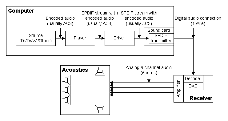
In some cases there is a possibility to transmit multichannel sound even when the pass-through transfer mode is unavailable (the format is not supported by receiver). To this effect, it is necessary to convert the format into a form understood by receiver:
Such model of operation enables to bypass many restrictions on the pass-through transfer mode. However, it is necessary to remember that coding to AC3 always results in quality loss (the AC3 format is a format of coding with losses, as well as e.g. the MP3 format), i.e. the main advantage of the digital connection turns out to be questionable. In these cases, it is recommended to use analog connection as it may ensure better quality.
This software product is distributed under the GNU General Public License v2, the text is appended as the GNU_eng.txt file in English and the GNU_rus.txt in Russian. The variant in Russian is provided as a reference only; in case of any discrepancies, the English version prevails.
This software product may be used only for demonstration and training purposes. Any use for other purposes may be prohibited in some countries. This product may be distributed freely, except for cases prohibited by the legislation.
This software product is distributed exceptionally with a hope that it will be useful; however, without any guarantees of operation on a specific equipment, of meeting any conditions, standards or needs. I do not undertake an assurance of twenty-four-hour (or any) support, of an error correction, of recovery of data lost due to operation of the program, of liability for spoilt hardware as well as for lost working time. I am not responsible for legality of multimedia products reproduced by this program.
This software product may be distributed in form of installation package ($download_bin) in CD collections or along with other programs. No author permission is needed for it. For codec-packs, it is admissible to distribute the filter as individual module.
The project needs your help! If you like the program, it enables you to solve your problems, you will use it at home or in your professional activities, and if you have ideas how to improve it, you may support the further project development.
A financial support is accepted at this address:
Any sum is important; this is not only money, but a moral support too.
You may support the project not only financially, I accept any help. In the first place, I need equipment for testing. E.g., a large number of problems relating to the SPDIF mode are caused by fact that I have absolutely no SPDIF equipment.
Besides, the project needs a site and its maintenance. In addition, first of all, a support of the forum is needed to provide a patient help to beginners as well as to identify really serious problems.
It is required to translate the documentation, as for large number of users neither Russian, nor English languages are the native ones. Unfortunately, interface translation is not planned yet, but translation of documentation is necessary.
| Copyright (c) 2002-2004 by | Last updated $date |